![]()
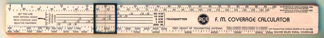
RCA FM Coverage Calculator
I picked this up at a Sackville secondhand shop for Can$8.00. It seemed like a nifty piece of RCA memorabilia. It works like a slide rule.
I have this notion that it might have come from an employee out at the RCI Transmitting Station. There used to be several RCA 50 kW shortwave transmitters out there, and it may be that somebody from RCA had sent this to one of the engineers as a promotional item. There never were any FM broadcast transmitters there, however.
Size: 355 mm x 38 mm (12" x 1.125")
The blue and orange fringes are just an artifact of my scanner, but the body of calculator itself is ivory painted wood.
|
Where
|
What it says
|
Huh?
|
|
| fine text in upper right |
Miles radius
of urban coverage area (1000 microvolts per meter)
Miles radius of rural coverage (50 microvolts per meter) |
The very top scale goes from 4 to 100 miles. The next
one down goes from 16 to 143 miles. "Microvolts per meter" is
just a standard unit of radio power. If you hold up one meter of antenna
wire (at exactly the right angle), this is how many millionths of a volt
are generated between the ends.
If you assume that 50 microvolts per meter (in the country) gives an acceptable quality signal at the receiver, you'll be able to calculate how far away you can reach. Urban settings are subject to things like additional interference, reflections and so on, so you need a higher power signal for the same reception quality. |
|
| left end of middle sliding part, with arrow |
Set this line over antenna
height |
This is the height on the tower where the antenna elements
are mounted. You move the middle section until the vertical line is over
the antenna height in the scale second from the bottom
|
|
| sideways text |
Turnstile antenna
layers
|
An antenna system can consist of several similar components stacked on top of each other. In this case, from one to six layers. The "selected equipment" is your combination of antenna layers and transmitter power. A "turnstile" antenna looks like a flat X on top of a mast, with four bars or wires sticking out horizontally at 90 degrees to each other. This give a coverage pattern that is supposedly omnidirectional, but is really more like a cloverleaf. They can be stacked one on top of the other. The idea behind stacking is not to get more power, but to direct the power more horizontally. Instead of a radiating pattern like a doughnut, (with much of the power shooting off into the sky) it flattens it out, more like a vinyl record. Most broadcasters are not interested in reaching people in airplanes. |
|
| middle of centre sliding part |
|
||
| text just below RCA logo |
Feet height
of transmitting antenna
|
The height numbers go from 100 to 5000. Higher is better,
so it's no accident that the top of structures like the CN Tower look
like a porcupine, with all the antennas. FM propagation is "line
of sight", so one factor is the curvature of the Earth.
|
|
| fine print below "FM Coverage Calculator" |
Rural coverage radius is correct to 10 percent Urban coverage radius is correct to 10 percent for transmitting antenna heights up to 1000 feet |
Weasel words. As one of my instructors said, "Antenna design is a Black Art. No matter how much calculation, design theory, and computer simulation you've gone through, you're up on the roof with a hacksaw, fine-tuning it." |
|
| right end, very bottom scale |
Square miles rural coverage |
The numbers on this scale go from 800 to 65000. I suspect
they added this scale because it gives impressively bigger numbers for
slightly more hardware. One rule of radiation is that in order to reach
twice as far, you need to crank out four times the power, so if you give
the coverage in terms of radius, the numbers just don't increase as quickly.
|
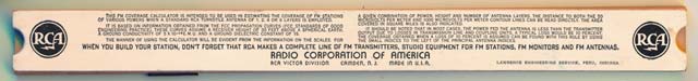
And on the back...
|
||||||||||||
Over to John Rose's Vintage Radio Home